A person new to the inspection and metrology of threaded parts finds a plethora of gauge types existing in the inspection of screws and nuts. Their terminology and significance can be confusing, but this article is meant to explain them in a simple way.
In production shops, the inspection of cylindrical parts (shafts or holes) for acceptance is quickly done using simple GO and NO-GO snap/ring gauges (for checking shafts) and plug gauges (for checking holes). They are mostly simple and easy to comprehend.
In the case of (screw/bolt) threaded parts, thread gauges are used in production shops where the “screws” (externally threaded parts) or the “nuts” (internally threaded parts) are to be quickly checked for acceptance. But when you consider the metrology (the science of measurement) of threaded parts as a whole, more than a couple of thread gauge types are involved; a novice in metrology may become somewhat confused with the terminology of the threaded gauges, their application, and their usage.
In this article, we shall try to understand the various types of thread gauges and their applications. This article deals with thread gauges used primarily in the shop for acceptance gauging of threaded parts.
Before that, a word about thread gauging practice:
In a threaded part, several features are involved – the thread’s major diameter, minor diameter, pitch diameter, pitch (in case of metric threads) or threads per Inch (TPI in case of Standard American Equivalent (SAE) threads), flank angle, etc. Normally, a GO / NO-GO type of threaded gauge will inspect a threaded part based mainly on the pitch diameter. As long as a GO gauge is answered (threads properly without being forced) and a NO-GO gauge is not answered, the threaded part is deemed to be accepted in totality.
But in some specific cases where the thread major diameter (for screws) or minor diameter (for nuts) is critical, separate, plain GO/ NO-GO gauges (as those used for measuring cylindrical parts) are also used in addition to a threaded gauges to determine the acceptance of a threaded part.
a) Thread plug gauge (GO and NO-GO):
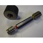
A thread plug gauge is used to check acceptance of a “nut” – i.e. an internally threaded part. For small threaded parts, the gauge will be double ended, with one end carrying the GO gauge and the other end, the NO-GO. For large parts, the two may be separate pieces. A thread plug gauge is designed to check the correctness of the pitch diameter (to the given pitch / TPI).
For acceptance of the part, the GO gauge should pass through the entire length of the nut, without requiring the use of too much rotational force. The NO-GO gauge can at the best enter into the nut, checked at both ends, over not more than 2 turns and NOT beyond.
(Fig:1 A thread Plug gauge)

B) Solid Thread Ring Gauge (GO and NO-GO):
A solid thread ring gauge is used to check acceptance of a “screw” – i.e. externally threaded part. The GO and NO-GO rings are normally separate pieces. A thread ring gauge is designed to check the correctness of the thread, to include thread depth and pitch diameter (to the given pitch / TPI).
For acceptance of the part, the GO ring gauge should pass through the entire length of the screw, without too much use of force. Ideally, the screw or bolt will thread completely through the gauge relatively easily. The NO-GO ring gauge can at the best enter into the screw over not more than 2 rotations and NOT beyond.
C) Adjustable Thread Ring Gauge (GO and NO-GO):
These gauges, too, are ring shaped, but they have a split and an adjusting and locking screw facility to finely adjust their right gauging size. For setting these gauges, “Setting plugs” are needed, which are discussed later.
Fig:2 Thread ring gauge Fig:3 Adj. Ring Gauge Fig:4 construction of Ad. Ring gauge

D) Thread caliper gauges (GO/ NO-GO)
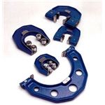
Though an external threaded part is best checked with a thread ring gauge, the use of thread caliper gauges (which are also called thread snap gauges) is also in practice. Some caliper gauges may be designed with roller type GO elements, which facilitate quick inspection by simple sliding of the threaded part, using gravity, through the GO rollers.
Though not as accurate as ring gauges in inspection, thread caliper gauges are preferred in mass production areas where screws need to be inspected considerably faster. A caliper gauge is much quicker for inspection as the parts are slid through the gauge rather than screwing-in as in ring gauges. The wear and tear thread caliper gauges is also less.
However, in places where caliper gauges are used, it is normally recommended to also have an additional thread ring gauge set, to perform inspection on random samples and ensure an additional layer of quality assurance.
Caliper gauges require “setting plugs” to set them to correct inspecting size which are discussed later in this article.
Fig: 5 Thread Caliper Gauge

The above four types of gauges are used on the shop floor for acceptance of threaded parts. In the next part of this article, we shall cover other thread gauges which are used mostly in the Standards Room, for checking and calibration of the aforesaid thread gauges.
Contact: Nina She
Phone: +86-13751010017
E-mail: sales@china-gauges.com
Add: 1F Junfeng Building, Gongle, Xixiang, Baoan District, Shenzhen, Guangdong, China